G1 Concept – Design Process
Written by Admin - 20th January 2019
Four years ago Chris Porter from GeoMetron Bikes/Mojo approached NICOLAI bikes in Germany with a very specific idea for mountain bike geometry in his mind. That was the beginning of a very fruitful collaboration which culminated in the creation of the current GEOMETRON G16 and its siblings the G13 and G15 trail bikes.
Fields of expertise
It became clear quite early on in the G1 design project that we had to team up with other specialists in the field to come up with the next step in bicycle design instead of everyone working on new ideas on their own. This partnership is based on sharing ideas as well as design and engineering expertise and so we are proud to present the G1 as the latest result of this collaborative effort.

NICOLAI are the European specialist when it comes to aluminium frame production. Nicolai have 25 years of bike frame building experience and have a fully equipped up to date CNC production facility in Germany. The range of experience, expertise, machining capabilities, welding and design capabilities in house are un-paralleled.
EXT are the Italian hydraulic and suspension specialists. Based in Vicenza in Northern Italy, EXT have longstanding experience in suspension technology on motorized vehicles incl. F1, World Rally Championship, World Touring Cars and ATV’s. Similar to the NICOLAI setup, EXT produce everything in situ in their HQ to better keep tabs on quality control and simple repeatability of damping levels and performance.
We at GEOMETRON bikes are specialists in analysing and improving the dynamic behaviour of bicycles focussing on the inter-relationships between the geometry and the suspension design. We moved into our new premises in Monmouth, South Wales, at the end of 2017 and in the same move we extended our R&D capabilities. We are now able to do the complete 3D frame design in house starting with 2D geometry drawings, linkage analysis up to a full manufacturing documentation.
Where do you start to make improvements to an existing bike?
Just as with any other engineering projects you start by listing things that could be improved based on your own experience with the product, testing days with customers and long- term customer feedback.
When we ask ourselves, from a customer perspective: what should a new bike bring to the table in order to get us hooked and make us want to invest in a new frame – it clearly needs features that stand out. A new colour or a new cable routing alone just isn’t enough.
A blank sheet of paper is always a daunting start point, but when you already have 4 years of experience with the GEOMETRON geometry and Nicolai strength and stiffness there are certain things that you are very happy with and you want to carry over.
Theory vs reality – up vs down
It all started with a couple of ideas we played around with in our Monmouth office, 2D geometry sketches in our Solidworks CAD system and some ‘artistic’ drawings on our whiteboard.
Once initial ideas were unleashed, the next step was to go back to riding bikes to analyse the behaviour of the ‘actual’ bike during pedalling. We had to check our previous pedalling behaviour analysis and findings from 4 years ago because of the ongoing development of new, wide range drivetrain systems and a shift in rider behaviour (in part driven by more capable bikes) to more natural, steeper terrain. Theoretical analysis of the linkage curve through the range of travel was also a big part since we were about to team up with EXT to develop a new shock for the bike.


A big topic that always came up during our meetings, aka ‘lunch laps’ was the steering behaviour and the ‘dynamic balance’ of the bike and the factors that played a role in defining it (e.g. head angle, fork offset, BB height, wheel size, suspension spring and damping settings). The dynamic analysis of a bicycle is usually based on abstract 2D models with an ‘assumed’ rider CofG, the anti-squat theory (which describes the influence of the drive train forces on the suspension) is a good example of this and shows how malleable that anti squat number can be. Justifiably so because the rider’s CofG is actually move-able, but given adjustments to bar, stem, saddle and suspension also, it’s clearly not really a precise science.
Whilst for our anti-squat analysis it is accurate to compare frames with a similar design like the NICOLAI G13, G15 and the GEOMETRON G16, this only works because we can back up the theoretical knowledge with real life testing and experience on various prototypes with different pivot locations and drive train setups (adding as much ‘craft’ as science to the analysis process). Literally hundreds of hours hard graft riding different types of climbs with different types of anti-squat set-ups and checking the effect of those changes on the bikes handling elsewhere in flat turns and steep turns.
So with rider position, riding style, trail choice and settings having such a big influence on the anti-squat numbers, to develop the bikes further it is almost inevitable to not only come up with a personalized suspension setup but a personalized anti squat setup as well. Some people like the rear end to compress a tiny bit on technical climbs just to track the ground and lift the rear wheel over obstacles. Some have very different requirements and need a stiff pedalling bike for long fire road climbs. ADJUSTABILITY is key to achieve this on a customer by customer basis.
Enough about uphill pedalling…we very much like our descents but with the theoretical model of steering behaviour we got ourselves in a bit of a pickle. When you lean the bike over for a turn or counter steer from upright to initiate a turn, the whole 2D world we use to map geometry just falls into pieces. It is a big achievement to describe the behaviour of a bicycle in a 3D world and even much richer motorbike companies with their highly paid and highly skilled staff are struggling with that. For those guys real world testing is still the key to making a 2 wheeled vehicle that is easy to handle and not one that has to be wrestled into a turn. On a bicycle off-road riding with your mates in the woods there’s not a single highly theoretical multibody math model or a mobile phone app that can keep up!

With all that in mind we started to try even more extreme or more conventional geometries on our G13, G15 and G16 production bikes this year with the help of angle adjust headsets, offset bushings and different length swing arms. The current G1 geometry was always the base we came back to. We always like the steering behaviour, we like the handling over rough ground and with some familiarisation and the right timing, the bike can be very playful.
The basic GEOMETRON geometry hasn’t changed a lot over the past 4 years. That includes the head angle, the BB height, the reach and the linkage characteristics like the outline anti squat values, the wheel path and the linkage ratio – basically the vital dimensions that define the behaviour of the bike. The top tube is lower than before, thanks to the availability of 185mm dropper posts. The chain stay length was always closely connected to the front centre length in our GEOMETRON geometry. That means that the longer the front centre (FC), the longer the chain stay length (CS) needs to be in order to keep a similar FC/CS ratio and similar front/rear weight bias throughout the different frame sizes. New for the 2019 model is that the seat angle changes with the frame size. So the horizontal “butt to rear axle distance” seated with an extended seatpost, is about the same for a rider on a small bike and a XL rider on a XL bike. Both riders now have the same starting point to tackle technical climbs without lifting the front wheel.
As an illustration of the range of settings we tried in those three G13, 15 and 16 bikes we tried from 320mm bb height all the way up to 355mm in 2 or 3mm increments. We tried 125mm travel up to 175mm travel. We used 27.5 wheels, 29 wheels and hybrid setups and we had a range of head angles from sub 60° to 65°. We achieved different ‘seat angles’ by chopping up seat clamps to try steeper and slacker versions of production angles (10mm forward or back on the seat rails is almost equivalent to 1° at the seat tube). We tried stem lengths from 25mm to 40mm and chainring sizes from 28T to 34T mated to cassettes ranging 10-50T to11-40T.
Again, the need for maximum ADJUSTABILITY of the individual geometry values is the key lesson we learned from our time on the descents.
Suspension, stiction, damping and travel range
After testing the variations on the trails in South Wales, we sat down and started drawing the production version of the G1. In a tight collaboration with NICOLAI we sent 3D CAD models of shock levers, shock mounts, frame gussets and swing arm parts back and forth until we were happy with the function and Nicolai with the machinability.


So now onto the things were we are seeing the biggest performance improvements: Compared to the G16 and G15 frames the family genes are very obvious – like linkage design and general frame appearance. From a technical and performance point of view the development around the rear shock holds the biggest improvement compared to its older siblings.
The collaboration with EXT earlier in the year was the most important factor to make this happen. Thanks to them we were able to design a frame and a coil shock as a unit. We asked EXT at the beginning of the year if they could implement a couple of our wish list of ideas we collected over the past years. Up until that point none of the big suspension companies were able to implement the ideas into a small scale production run of a rear shock. To our surprise it didn’t even take EXT a day to reply with positive feedback that they are definitely on board. With all the technology we intended to squeeze into the shock we couldn’t avoid the move to the metric 230mm length. Who remembers the press release a couple of years back that stated “New metric shock sizing makes room for big improvements in shock technology”?

Well, thanks for that! We are actually using the metric standard now according to what the initial idea behind the metric sizing was – to increase the available space in the shock to implement new damping solutions. We worked closely with EXT and tested the G1 prototypes in Italy, Spain, the UK and Germany in order to bring the progressive linkage ratio and the damping tune together as a package. There is some really exciting technology packed into that shock but to do it justice, it will get its own separate blog post to explain everything in detail.

One bike stable? Finally?
Another point very high on our priority list was the ability to adjust the frame to different wheel sizes, adjust the geometry (like BB height, head angle etc.) and change the amount of rear wheel travel. The travel range we were aiming for with the 230x65mm shock is 160mm – 175mm. There can be multiple reasons for changing the wheel size. You could set up the G1 as your UK trail centre 29er bike throughout the year and for your annual trip to Morzine you pop on a beefy triple clamp fork and 27.5 wheels and switch to the long travel setting for example. We can reduce the travel even further via shock stroke reducers to bring it down to a minimum of 140mm.

We always encourage our customers to come around and do a test ride on the bike. During those test sessions, we make adjustments to the suspension components and basically try to set up the rider as comfortable as possible on the Geometron. Even micro adjustments like setting up the BB height just 3mm higher have now become very easy with the new frame options.
With some very good results during the initial riding test, more ideas were added to the list of requirements. The cable routing was a requirement that we worked on because of customer feedback. The majority of our customers didn’t want internal cable routing at all, least of all for the brake hose and the shifting cable. For the ease of maintenance and for a quick hassle free swap in a bike shop or at a race, the brake hose and the shifter cable are routed completely on the outside of the frame. That means you can take off the brake without opening the brake circuit. The cables are clamped between two small CNC machined clamps and the cable doesn’t touch the frame tube at all. So even if the frame is really muddy and gritty the cable won’t wear through the coating or the actual frame material.

So there you have a brief rundown of our design process! Hope you like the result!
So overall, what changed and why?
-To achieve the design aims of performance and adaptability whilst offering increased strength and simplicity we changed a lot of things! In fact, each component from the rear dropouts forwards has changed.
-The outline silhouette of the bike retains the Nicolai/GEOMETRON family values so much that it is easy to miss the scale of the changes…
-Head tubes: largest sizes have smaller head tubes than before to allow a lower bar for some more aggressive riders. XXL frame size from 170mm to 150mm
-Seat tubes: lower seat tubes to reflect availability of longer dropper posts.
-Top tubes: lower standover height due to lower seat tube
-Down tube: Bigger stronger downtube to accommodate DH forks as an option, no holes drilled on the high stress centre line. Holes = the weakest point…
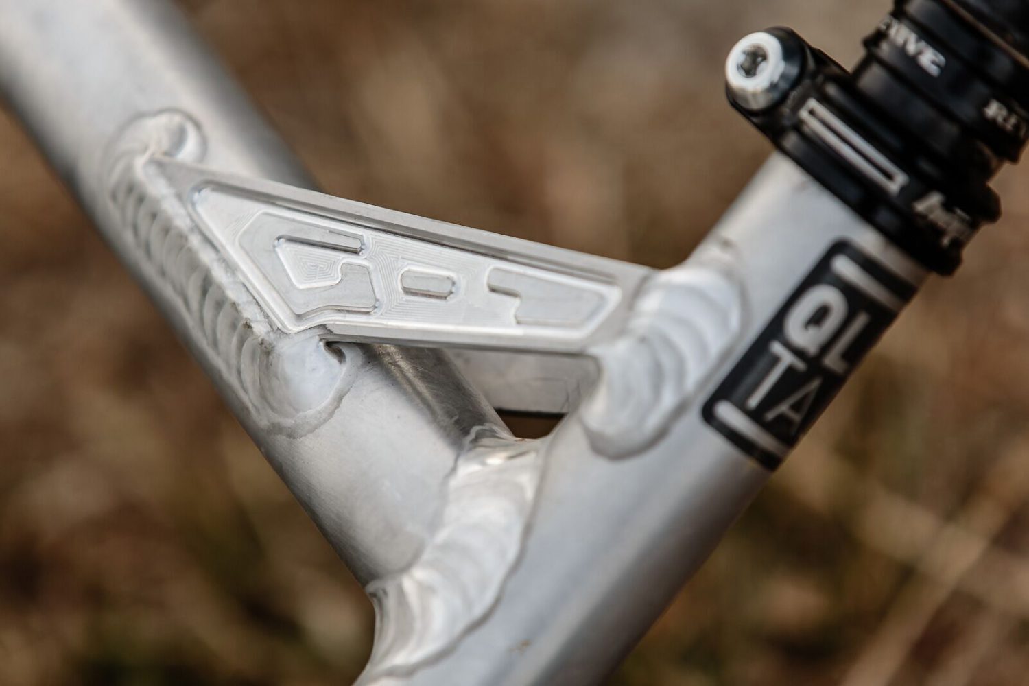
-ISCG tabs: we moved the ISCG tabs out to meet the new Boost chainring standard so we don’t have to use loads of washers!
-Swingarm yoke: wider bearing spacing for more strength, stiffness and longevity and to accommodate different wheel sizes.
-Seat stay mutators: To allow simple wide range adjustment of seat stay length to accommodate all of the geometry options necessary for wheel sizes, travel options and individual rider adjustments
-Linkage rocker: re-designed to allow two different shock mount positions for 160 and 175mm rear travel and to accommodate EXT bespoke shock with Spherical bearings
-Cable routing: new bolt on cable clamps designed to keep cable away from frame and eliminate the need for dismantling brake hoses for assembly, maintenance or last minute race prep swapping! Internal seatpost cable routing means we still need one internal cable, but we have an internal feature to make threading the internal cable easy and we put the exit in the same place as the cable clamp at the head tube. See also no holes drilled in downtube.
Please check our Blog over the coming weeks. We will get more into detail like the technology that is hidden inside the EXT V3 shock or our personal test setups we tried over past couple of months.
Figure 1/7/8 provided by Alex Luise
Figure 2 provided by Sandy Plenty